
Installation Instruction
Electrofusion couplers & fittings
These instructions serve as a guide for the proper installation of Electrofusion couplers and fittings. The user is obligated to comply with the locally applicable regulations, guidelines, and standards.
More about our electrofusion fittings To our product databaseThe following equipment is required:
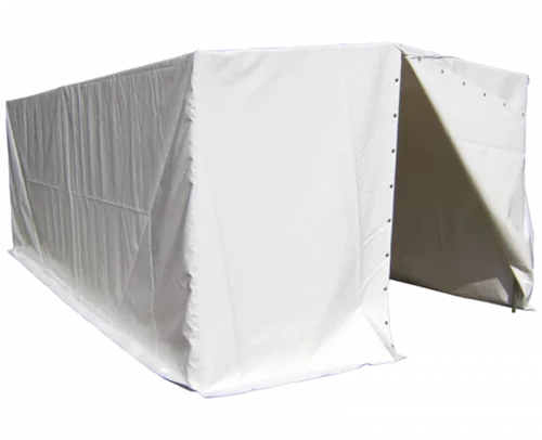
Welding tent
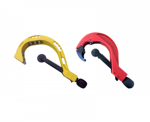
Pipe cutter

Scraping Tool

PE cleaner

Re-rounding clamps

Electrofusion machine
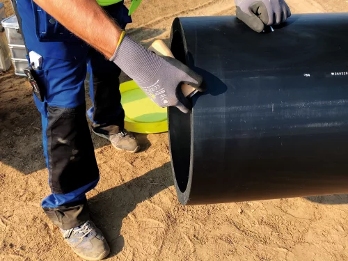
1. Preparation for Welding
Cut the pipes to be welded at a right angle behind the bent pipe area, deburr and clean them thoroughly. Cover any openings that are not to be welded with protective caps.
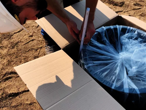
2. Mark the peeling area
Measure the section to be peeled [insertion depth (L1) = half the total length (L)] on the packaged product and mark it on the pipe with a 2–5 cm addition.
3. Check the pipe diameter
Check the pipe diameter with a acircumferential tape measure before and after peeling. If there is any out-of-roundness in the weld area, use rounding clamps.

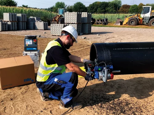
4. Remove the oxide layer
Use a pipe scraper machine to remove the oxide layer from both ends of the pipe. Observe the minimum material removal of 0.2 mm and the maximum permissible reduction in wall thickness.
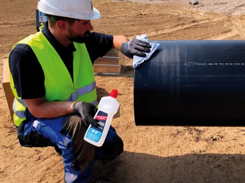
5. Clean machined surfaces
Clean the machined pipe surfaces with a DVGW VP 603-certified PE cleaner and a clean, lint- free cloth. Allow pipes to dry completely; avoid contamination to dry completely and avoid contamination.
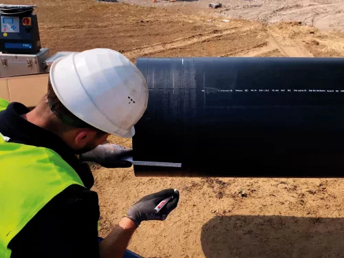
6. Mark the insertion depth
For products without a center stop, mark the insertion depth (L1) = ½ of the total length (L) again with a permanent marker.
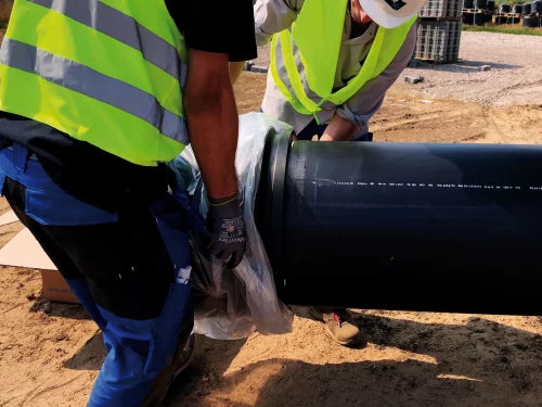
7. Cleaning
Clean the weld surfaces of the fitting, remove the product from the packaging (do not touch it), and slide it straight in until it reaches the mark or the center stop.
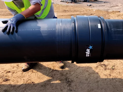
8. Repeat the process
Repeat the procedure at the other end of the pipe, ensuring that the coupler is properly aligned (max. 3 mm annular gap). Protect annular gap from dust, dirt, and moisture
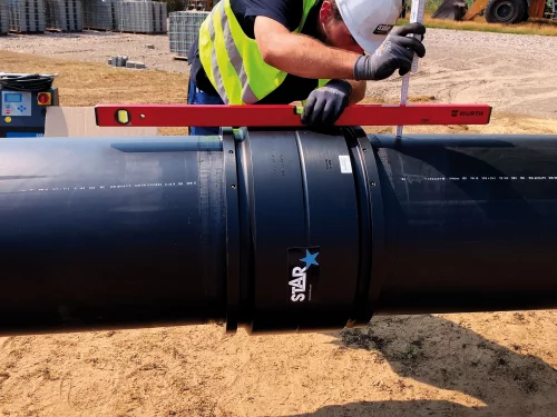
9. Positioning
Ensure that the component is positioned without stress (no bending or self-weight). Use retaining clamps and supports if necessary.
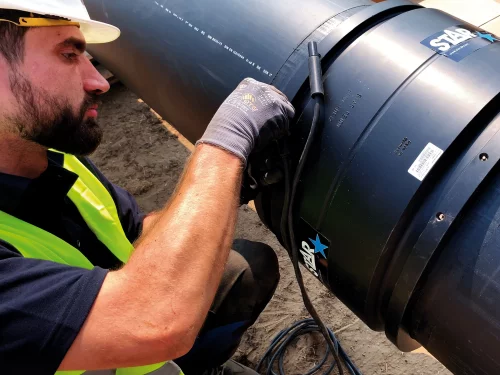
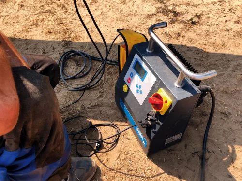
10. Start welding
Perform, check, and monitor the welding process in accordance with the welding machine manufacturer’s instructions.
11. Check the weld
After welding, check the device status, remove the welding cables, and ensure that the system is deenergized until the cooling period has ended. Only then should you remove the clamps and supports.
12. Installation complete
Do not backfill the pipeline trench until the pressure test has been passed.


